
Traces
 Traces are added after you place component footprints and set up nets. (strongly recommended)
Board tracing or routing is the process of placing traces.
When routing your PCB it is recommended to:
Traces are added after you place component footprints and set up nets. (strongly recommended)
Board tracing or routing is the process of placing traces.
When routing your PCB it is recommended to:
- Maintain a safe distance between traces and pads.
- Use the widest practical trace width.
- Minimize trace length.
- Use trace angles of 90 and 45 degrees.
Drawing Traces
Drawing Traces is the process of adding circuit traces to your board design in order to complete the desired electronic connections. You can draw traces as straight lines, polylines, rectangles, polygons, circles and arcs. Although traces generally go on a copper layer, you can use traces on the silkscreen layer to show the shape of a component.
To create a trace manually:
- If you created electrical nets prior to drawing traces (strongly recommended), activate display of the nets as a guide to ensure you connect the correct pins: Click left toolbar | Change Layer Properties | Net Layer | Visible.
- On the left toolbar select Trace tool, Circle tool, or Arc tool.
- In the left toolbar enable Snap To Angle or hold the Ctrl key if you want to constrain traces to multiples of 45 degrees (generally recommended).
- On the Property Bar select the layer where you want the trace to appear.
- Click at the start of the trace, at each corner if needed and at the end point. To change trace layer press “L” button.
- Right click when finished.
Often, there is no way to draw a trace on one side of the board due to other traces or footprints in the way. When this occurs, add a Via and continue the trace on the other side of the board. You can use additional vias along the route to the end destination.
Note that traces on one layer can pass directly across surface mount pads on another layer without concern of electrical connection.
To reshape a trace, select it and drag one of its line segments or elbow nodes (where two traces meet).
To add a node to a trace, double click the trace where the node to be added.
Autoroute mode
PCB Autorouter
- Create nets if not already done.
- Click Tools | Route | Route All.
- Any connections the auto router fails to make will be displayed by unresolved Logical Connections lines (if enabled). Create those connections manually.
- Click Tools | Route | Router Settings.
- The router settings dialog appears:
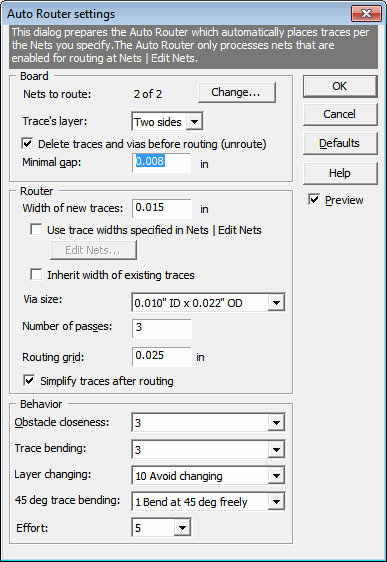
- Enter the desired parameters:
Nets to route Number of nets to route. Click Change… to go to the edit nets dialog to choose nets to be routed. Number of layers Number of copper layers on which you want to auto-router to place traces – usually “Two sides”. Minimal gap Minimum distance between conductors and between conductors and other copper objects. Smaller values improve the chance of fully routing your board. Width of new traces Width of traces created during the routing process. Smaller values improve the chance of fully routing your board. This parameter will not affect existing traces. Use individual trace width for each net Check to make auto-router use trace widths assigned for each net individually. Click the “Edit widths…” button to go to the Edit nets dialog to specify the trace widths. For a net that doesn’t have a trace width specified, the value “Width of new traces” will be used. Number of passes The number of times the auto router will try to route your board. Higher values improve the chance of fully routing your board but take longer to complete. Routing grid Similar to the snap grid, the routing grid specifies the distance between imaginary grid lines along which the auto router will place conductors. Lower values improve the chance of fully routing your board but creates a higher density of traces and takes longer to run. Higher values increase the chance to get an ugly layout with overcrowded traces, useless extra traces, etc. Obstacle closeness Affects closeness to obstacles such as pads. Lower values usually improve the chance of fully routing your board but places traces closer to obstacles. Trace bend Affects the number of bends. Lower values usually improve the chance of fully routing your board but increases the number of bends in traces. Layer change Affects the number of vias. Lower values usually improve the chance of fully routing your board but increases the number of vias. 45 deg trace Affects the number of 45 deg trace segments. Lower values usually improve the chance of fully routing your board but increases the number of 45 degrees trace segments. - Click OK
- Create nets for the footprint if not already done.
- Click the footprint to select it.
- Click Tools | Route | Route Footprint.
- Right click the logical connection or double click it.
- Choose “Auto route connection…”.
- The Auto Router dialog appears.
- Enter the desired parameters.
- Click Route.
To “unroute”, choose Edit | Undo.